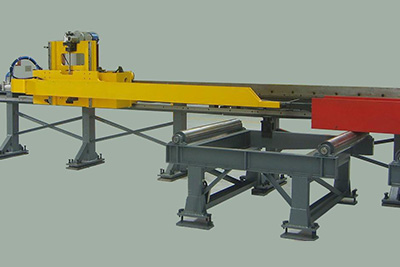
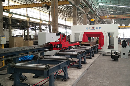
CNC beam drilling machine SWZ1000
Machine application:
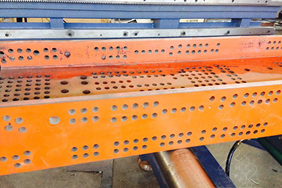
SWZ1000 CNC beam drilling machine is widely used in buildings, bridges, power plants, boilers, stereo garage, offshore oil well platform, tower masts and other steel structures industry, especially suitable for H-beam steel structure, channel steel, with high precision and easy operation.
Machine configuration:
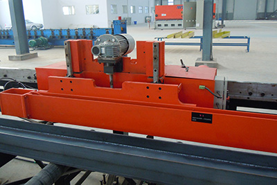
Machine is composed of frame, 3 CNC slide tables, 3 drilling heads, clamping device, inspection device, cooling system, chip conveyor etc.
Machine features:
1.Frame is welded from high quality steel, through finite element analysis, aging treatment and enhancement processing, improves static and dynamic strength, ensures machine processing accuracy.
2.Three slide tables, six CNC axis, guided by precision linear guide rail, driven by servo motor and ball screw.
3.Three drilling heads work simultaneously or independently, realizes automatic quick speed regulation.
4.Hydraulic clamping device, for workpiece clamping and pressing in horizontal and longitudinal directions.
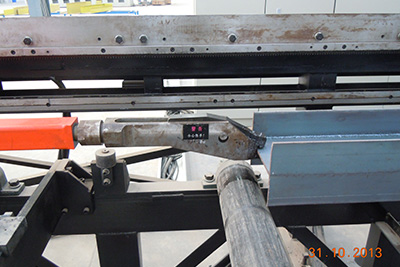
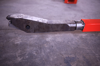
5.With width and height inspection device, automatic compensation function of irregular workpiece, improves processing accuracy.
6.Air-mist cooling, less coolant usage, saves cost and reduces drill bit wear.
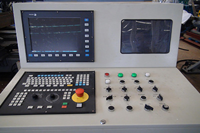
7.Self-developed program based on Windows operation system using VB6.0 software, for program edit, transmission, process monitor, parameter adjustment.
Parameters list:
| Name | Unit | Parameter values | ||
|---|---|---|---|---|
| size | H Beam | mm | 150x75~1000x500 | |
| Thickness | mm | ≤80 | ||
| Length | m | 15 | ||
| Short-material restrictions | mm | Automatic processing ≥3000 | ||
| manual processing:690~3000 | ||||
| Spindle | numbers | unit | 3 | |
| Drill size | The fixed side and moving side | mm | ¢12~¢26.5 | |
| Intermediate unit | mm | ¢12~¢33.5 | ||
| Main shaft rotation speed | r/min | 180~560 | ||
| Main shaft taper | / | #3 and #4 Morse taper hole | ||
| Axial stroke | The fixed side and moving side | mm | 140 | |
| Intermediate unit | mm | 325 | ||
| Axis to the feed rate | mm/min | 20~300 | ||
| Moving distance | Each spindle in the direction of length of the workpiece | mm | 520 | |
| Both sides of the spindle in the vertical direction | mm | 35~470 | ||
| Intermediate unit in the direction 0f the workpiece width | mm | 45~910 | ||
| Cooling method | Compressed air + cutting fluid | / | / | |
| Air supply pressure | MPa | ≥0.5 | ||
| Processing accuracy | Hole group adjacent Pitch error | mm | ≤0.5 | |
| 10 meters adjacent to the accuracy of the feeding distance | mm | ≤1 | ||
| Motor Power | Spindle rotation of three-phase asynchronous motors | kW | 4x3 | |
| Intermediate unit X-axis servo motor | kW | 1 | ||
| Intermediate unit Z-axis servo motor | kW | 1.5 | ||
| Fixed side,movable side X-axis servo-motor | kW | 1x2 | ||
| Fixed side,movable side Y-axis servo-motor | kW | 1.5x2 | ||
| The mobile pallet three-phase asynchronous motor | kW | 0.55 | ||
| Overall size | L x W x H | mm | 4400x2400x3500 | |
| Net weight | kg | About 7000 | ||

